gen_cross_section
What is gen_cross_section?
gen_cross_section is a tool for creating PNG images of chip layout cross sections. Layout tools use a plan view but sometimes it is useful to be able to look at the cross section of a particular part of a design, especially for people new to layout.
It doesn't provide a true cross section because it assumes that all layers are perfectly planar.
Using gen_cross_section
You'll need to create two files to match your process - palette.txt and layers.txt which describe the colours to use for the cross section and the depth information for the cross section.
After you have those files, you need to create the cross section information to pass to gen_cross_section. If you are a Cadence Virtuoso user then there are functions provided that will allow you to generate a cross section directly from the layout window. Users of other tools will have to generate the file themselves - information on the format is provided in the download.
Example
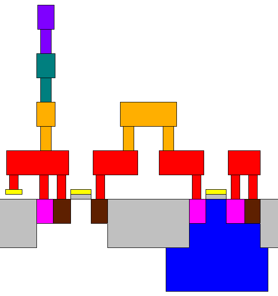
A cross section from a generic p-substrate 4 metal 1 poly process is shown in the picture (click to enlarge):
Downloads
- gen_cross_section 20090110 (12kB) (GPG Signature)
Repo
License
The C code making up gen_cross_section is licensed under the GNU GPL
Contact
gen_cross_section was written by Roger Light, with significant portions of the Cadence SKILL code written by Jim Newton of the Cadence VCAD team. Questions, bug reports, suggestions are very welcome.
Contact me on roger_atchoo_org. Replace the _ with @ and . respectively.